Smol But Effective

GERRAWAY-BY-CLASS ORBITAL SERVICE VEHICLE

Operated by: The canine orbital mechanics of regular orbital mechanics.
Type: Orbital transfer/service vehicle.
Construction: Horizon Cageworks, ICC

Length: 2.2 m
Beam: 1.7 m
Dry mass: 784 kg

Gravity-well capable: No.
Atmosphere capable: No.

Personnel: 1 smart dog (prosophont bandal partial uplift)

Drives:

  • Propulsion Dynamics, ICC HX-3 Husky low-thrust orbital maneuvering engine
  • Propulsion Dynamics, ICC cold-gas reaction-control assembly
  • Horizon OrbitSpace, ICC reaction wheels

Propellant: Liquid hydrogen/liquid oxygen mix.
Cruising (sustainable) thrust: 0.25 g
Δv reserve: 1,350 m/s

Sensors:

  • Orbital Positioning System
  • Star tracker
  • Passive EM array
  • Short-range collision avoidance and docking radar
  • Transponder

Other Systems:

  • Cognitech, ICC/Family of Species, ICC “Radio Sniffer” audio-olfactory merkwelt translation system
  • Cognitech, ICC/Family of Species, ICC “Starlight Barking” multimodal communications system
  • Exogenesis, ICC AI pilot-assist and remote override system
  • Omnidirectional radio transceiver
  • 3 x Extropa Energy, ICC accumulators
  • Systemic Integrated Technologies radiative striping/solar power collection systems
  • 1 x Extropa Energy, ICC hydrogen-oxygen fuel cell
  • Canned (non-regenerative) life support; CO₂ scrubbers
  • High-intensity LED work lights
  • 4 x fixed-point multipurpose, interchangeable-tool work arms (Horizon OrbitSpace, ICC)
  • optional satellite servicing kit, tool platform, and component rack (Horizon OrbitSpace, ICC)
  • optional interchangeable drop tanks for use with refueling probe
  • optional debris-collecting shield, basket, and tow cables

DESCRIPTION

The Gerraway-By-class of “micro” orbital service vehicle was a unique oddity brought to life by the circumstances of the early space era, and a chance meeting at the Look Out Below Café and Bar. Specifically, a wide-ranging discussion over several beers between some of the celestime architects from Horizon Cageworks, a number of gentlesophs working in various orbital industries, and a trainer of working bandal – and more specifically their “smart dog” variants who had undergone stage one uplift – who happened to be visiting the platform at the time. The topic was the increasing amount of grunt work – refueling satellites, performing basic maintenance, debris collection – that maintaining orbital industry required, and how inefficient it was to continue carrying this out by hand.

The result, a design outline found scribbled on a pile of napkins delivered to the Horizon offices the next morning, was the Gerraway-By.

In its essentials a shrunk-down version of the Minnal-class workpod – refactored so that one or two Gerraway-Bys could be carried by a Minnal, or several by an OTV – the Gerraway-By was intended as a means to bring our old friends with us into the space age. While AI was not quite ready for independent use performing the necessary tasks, it was more than capable of operating in conjunction with a well-trained working bandal, and their eldrae supervisor, to command a small service vehicle operating from a larger ship.

Combined with the work into uplift carried out by Family of Species and Cognitech’s beginning research into merkwelt translation easing interface difficulties, the timing was perfect for an entirely new kind of spacedog to take their place shepherding Eliéra’s increasingly crowded low orbitals, and a new era of partnership was born.

Nope, It’s A Bridge

Many of you, gentle readers, are also devotees of the Atomic Rockets web site. (As well you should be, if you are interested in matters rockety.) And, of course, you may have noted the Atomic Rockets Seal of Approval off in the right-hand column.

But today I’m going to talk about a place where I find myself, and the ‘verse, disagreeing with it. Specifically, with “It is a CIC Not a Bridge“. For convenience, I’m going to quote from it here:

That round room in the Starship Enterprise? The one they call the “Bridge?” Wrong term, that thing is a Combat Information Center (CIC). On a real wet-navy vessel, the bridge is a tiny two-station place used to control the the movement of the ship. It only had stations for the navigation and helm.

In other words, the “bridge” on the Starship Enterprise is that little console that Sulu and Chekov sit at.

The CIC is where all the data from the sensors, scoutships, intelligence agencies, central command, and other ships is gathered and evaluated. The important information is passed to the captain along with tactical suggestions. Exactly the way Uhura, Scotty, and Mr. Spock pass information and tactical suggestions to Captain Kirk.

http://www.projectrho.com/public_html/rocket/misconceptions.php#id–It_is_a_CIC_not_a_Bridge

So, here’s the thing. It’s actually slightly more complicated than that. There are three places on a wet navy vessel all of which do things that people think of as functions of “the bridge”.

There is the CIC, as described above. It’s the information-gathering and decision-making center.

Then there is the wheelhouse, which is where the ship’s movement is controlled from. This, on ships that had a bridge, was usually buried down inside the hull or beneath the superstructure – for one simple reason. You don’t want it shot off. If you lose the wheelhouse, you can’t command the ship any more, so you don’t want it somewhere vulnerable.

And then there is the bridge, which is the place you conn the ship from. It’s up high at the front of the superstructure with generous wings, etc., because its requirement is that you be able to see what the ship’s doing in order to command it.

(On a merchant ship, you probably don’t need a protected CIC, and since you don’t expect anyone to shoot your bridge off, you may have the engine-room telegraphs and wheel up there in one place. On navy vessels, on the other hand, instead of passing engine orders and steering directly, you have a bridge talker yelling “Port 40! Half ahead both!” down voice tubes to the wheelhouse.

On the other hand, the bridge is also exposed to heavy weather, so merchies that expect to encounter the rough stuff may still have a separate wheelhouse. This was actually where they first came from.)

In a historical digression, incidentally, the original bridge is an evolution of what was originally the quarter deck, the raised deck at the stern, on sailing ships. When it became more important to avoid your own smoke than see what your sails were doing, which is to say, as we moved from sail to steam, the raised area moved for’ard and became the bridge as we know it today.

As for the wheelhouse, that came from sailing ship designs in which the poop deck (the highest deck at the stern, typically forming the roof of the stern cabin) was extended forward to cover the quarter deck and the ship’s wheel, on the entirely reasonable grounds that in a storm, it’s easier to steer without being out in the full blast of wind and wave, and in battle, it’s much easier to steer if you have some protection from being shot.

So let’s bring this back around to starships.

You don’t need a bridge in the above sense. As it says further up that page, Rockets Don’t Got Windows – given space ranges and instrumentation, you are never going to be trying to conn the ship with your Mark I Eyeball, which is essentially what a bridge up high is for. Your best view is going to come from sensors, but they can be read just as easily from the CIC, buried deep in the center of the hull for maximum protection.

(Why did the Enterprise designers perch the bridge right up at the top of the saucer, with about three feet between the back of the fancy digital sensor-feed-showing viewscreen and hard vacuum, right where any Tom, Dick, or Kang could shoot at it conveniently? Were they all Romulan spies?)

Do you need a separate wheelhouse? Well, given that starships are certainly going to have fancy electronic controls rather than the hydraulic/pneumatic/etc., systems that imposed constraints on the position of wet navy wheelhouses vis-a-vis the CIC – usually buried down in the bottom of the ship where the armor is thick – I’m going to say probably not. The CIC’s already in the safest place, per above.

(You may have a maneuvering room, as they call the place on submarines, where the engineers translate your requests into detailed instructions to the engines, and given that a starship ACS is probably also rocket engines of some sort, that may also be handled from there – but that’s a different function.)

You are going to have a CIC, because you still need somewhere to coordinate information, make decisions. In my opinion, it will probably also be the wheelhouse (after all, as in the Enterprise example above, it’s just one console, and since the maneuvering orders are going to come from the officer on watch in the CIC anyway, why make him shout any further than he has to?).

The only question is whether it will be called the CIC. The above (combined CIC/wheelhouse) is essentially the arrangement they use on submarines today (where it is called the control room; the bridge is the place you can stand at the top of the conning tower when the boat’s on the surface).

That may be likely nomenclature for starships, too. (Nothing especially that civilian starships are unlikely to have a Combat Information Center.)

On the other hand, the Imperial Navy, and their merchant tradition, call it the bridge. Why? Well, unlike our submarines, there isn’t another bridge somewhere to clash with it – and you get your best view of what’s around from it – and in the meantime, it’s a name that’s got centuries, indeed millennia, of tradition behind it as The Place From Which Ships Are Commanded. It’s a word, in a nutshell, that’s got weight.

And since you’re combining all the functions back together, as they were in the beginning, that counts plenty.

The quarter deck, on the other hand, that’s somewhere else.

To The Moon!

(Turns out the first ship I want to do isn’t one of the ones anyone asked for. Oh, well.)

SILVERFALL-CLASS LUNAR EXPLORER – BLOCK II

Operated by: Spaceflight Initiative
Type: Early exploration vessel.
Construction: Spaceflight Initiative.

Everyone’s heard of the Silverfall-class explorer, the starship that first carried eldrae from Eliéra to its moons. (A surprisingly large number of them have visited the museum out on Seléne where Silverfall Four — Moondancer — rests in state out on the regolith, where she was flown to her resting place by her original crew, and is kept in flight-ready condition by her many admirers.)

The design discussed here is of the Block II variant of the Silverfall-class, which incorporates the modifications made to improve performance and livability after studies performed on Silverfall Zero and Silverfall One, and whose two examples can be considered representative of the class, including as they do the actual craft, Moondancer, which made the first landing on Seléne; later design revisions included a number of specialized variants, but made no further changes to the basic design.

Length: 42.2 m, of which:

  • Mission module: 12.2 m.
  • Engineering frame: 18 m (overlaps with propulsion module)
  • Propulsion module: 12 m
  • Shock absorbers and pusher/ground plate: 12 m

Beam: 12 m (mission and propulsion module); 22m (widest point)
Mass (fueled): 616,200 kg

Gravity-well capable: Yes.
Atmosphere-capable: No.

Personnel: 2 required, as follows:

Flight Commander
Flight Director/Engineer

Accommodates 6 further mission specialists.

Drive: Silverfall-specific fission pulse drive with laser trigger; cold-gas attitude control and landing system.
Fuel: Plutonium coated fuel pellets.
Cruising (sustainable) thrust: 2.4 standard gravities
Delta-v reserve: 16,800 m/s

Drones: Simple automation only.

Sensors:

Star tracker
Inertial tracking platform
Passive EM array
Short-range collision-avoidance and docking radar
Mk. 1 Eyeball

Weapons: None, unless you count the drive.

Other systems:

Thorium pebble-bed power reactor
Omnidirectional radio transceiver
Communications laser
Whipple shield (habitable area only)
Canned (non-regenerative) life support; CO2 scrubbers
Redundant flight control systems
NaK pumped-loop high-power radiators and maneuvering heat-sinks
NH3 low-power radiators

Small craft: None.

DESCRIPTION

The original Phoenix-class orbiter was once described as an explosion in a girder factory, and its smaller cousin, the Silverfall, maintains much of that look, despite at least some improvements in elegance between the designs. That, and that unlike the Phoenix, the Silverfall was designed as a pure space vessel, intended to be built at and operate from Oculus Station in Eliéra orbit, and to land only on airless Seléne and Elárion.

The layout of the Silverfall-class can be divided into four sections: the upper mission module, the engineering frame which sits atop and wraps around the propulsion module, and the shock absorber/pusher plate section at the bottom.

At the top, the mission module is divided into three tail-lander decks with plenum space in between. The uppermost deck, topped by a blunt cupola and surrounded by the various navigational and communications antennae, contains semicircular bridge and mission management sections, surrounded by the ship’s avionics. From it, an axial passage descends through the next two decks, terminating in a small engineering space (housed in an aft projection) where the mission module connects to the primary thrust truss of the engineering frame. A secondary access tube, normally depressurized, runs down from this passage through the engineering frame.

The second deck houses three pie-segment areas; the ship’s laboratory, workshop, and main stowage area. Opposite the stowage area, between the laboratory and workshop, a secondary airlock provides maintenance access while in flight to the exterior of the ship (with a ladder down to the upper levels of the engineering frame), and is the main access point when the starship is docked.

(Opposite this airlock, centered on the mission module’s vertical axis, is the gold plaque bearing the Imperial Star and the stylized rocket-and-crescent-moon of the Spaceflight Initiative, with beneath them the various names and logos of the various contributors making the Silverfall mission possible.)

The third, lowermost deck contains the crew quarters, divided into a number of modular pods, along with the galley, central mess, ‘fresher, and a small medical bay.

Six meters below the mission module is the propulsion module, a heavy steel capsule containing the guts of the nuclear-pulse drive that powers the Silverfall. For the most part, however, it is hidden by the engineering frame which wraps around and atop it, a mesh of trusses containing, most notably, the six pellet silos, evenly spaced around the ship, containing the plutonium fuel pellets, and the spherical tanks of cold-gas propellant and life-support supplies.

The lower surface of the engineering frame (along with that of the propulsion module) is the solid sheet of the protective shadow shield, protecting the upper sections of the craft from radiation produced by the pulse drive. The secondary access tube descending from the base of the mission module connects to the primary airlock, located directly above the edge of the shadow shield vertically beneath the secondary airlock, and from which a descent ladder can be lowered once the drive shroud is in place.

At its edges, laser modules extend past the edge of the shield to trigger the explosive coatings of the fuel pellets; just within those edges, sealed slots permit the segmented drive shroud to be lowered after landing, surrounding the mechanics of the shock absorbers and pusher plate, to protect disembarked astronauts from residual drive radiation.


The Sapphire Coloratura: Revealed!

Inspired by a passing comment on the Eldraeverse Discord, we now present a galari starship, the Sapphire Coloratura-class polis yacht; the favored interplanetary and interstellar transport of all sophont rocks of wealth and taste.

SAPPHIRE COLORATURA-CLASS POLIS YACHT

Operated by: Galari groups requiring luxurious private transit.
Type: Executive polis yacht.
Construction: Barycenter Yards, Galáré System

Length: 96 m (not including spinnaker)
Beam: 12 m (not including radiators)

Gravity-well capable: No.
Atmosphere-capable: No.

Personnel: None required (craft is self-sophont). Can carry an effectively arbitrary number of infomorph passengers.

Main Drive: Custom “dangle drive”; inertially-confined fusion pellets are detonated behind a leading spinnaker, the resulting thrust being transferred to the starship via a tether.
Maneuvering Drive: High-thrust ACS powered by direct venting of fusion plasma from power reactors; auxiliary cold-gas thrusters.
Propellant: Deuterium/helium-3 blend (pelletized aboard for main drive).
Cruising (sustainable) thrust: 7.2 standard gravities
Peak (unsustainable) thrust: 7.5 standard gravities
Maximum velocity: 0.12 c (based on particle shielding)

Drones:

4 x galari body-crystals; since the galari are ergovores, any galari passenger or AI system may use these for EVA purposes.

Sensors:

1 x standard navigational sensor suite, Barycenter Yards
1 x lidar grid and high-sensitivity communications laser grid, Barycenter Yards

Weapons:

Laser point-defense grid.

Other Systems:

  • Cilmínár Spaceworks navigational kinetic barrier system
  • 4 x Bright Shadow secondary flight control systems
  • Kaloré Gravity Products type 1MP vector-control core
  • Systemic Integrated Technologies flux-pinned superthermal radiator system

Small craft:

5 x minipoleis (no independent drive systems; local accumulators only)

DESIGN

The Sapphire Coloratura was intended to be a shining jewel in the crown of galari starship design, so it is perhaps fitting that it indeed resembles a shining jewel, the translucent crystal of its main body throwing sparkles of rainbow light everywhere when it chooses to fly close to stars, or when it is illuminated by the fiery blasts of its main drive.

The main body of the ship is similar to, in many ways, the galari themselves; a sixteen-faceted crystal, with eight long facets facing forward to the bow tip, and short, blunter facets facing aft towards the mechanical section, a gleaming metal cylinder with a rounded-off end taking up the remaining two-thirds of the starship’s length.

To proceed from fore to aft, the bow tip of the ship is capped with metal, housing the core mechanisms of the dangle drive; the sail deployment system, tether terminus, pellet launcher, and ignition lasers.

From our Earth perspective, this drive is very similar to the Medusa-type Orion; thrust is delivered to the starship via a 216 m diameter spinnaker “sail” on a tether ahead of the craft. Rather than dedicated pulse units, the drive projects pelletized D-3He charges ahead of the craft to the focal point of the spinnaker, where inertially-confined fusion is initiated by the ignition lasers, reflected to surround the pellet by the inner surface of the spinnaker. The resulting nuclear-pulse detonation accelerates the craft, smoothed out by the stroke cycle of the tether (see above link).

The main crystal body of the craft is essentially a solid-state piece – save for cooling labyrinths and the axial passage required by the drive – of galari thought-crystal: a substrate which holds the ship’s own intelligence, those of all passengers and any crew needed, along with whatever virtual realms, simulation spaces, or other computational matrices they may require. As such, there is little that can be described by way of an internal layout; most polis-yachts are unique in this respect.

The “waist” – broadest point – of the body is girdled by a machinery ring, containing within it the four fusion power reactors (multiple small reactors were preferred for extra redundancy by the designer) with the associated ACS, and at points between them, the backup flight control systems, navigational sensor suite, and other small auxiliary machinery.

At the aftmost point of the main body, where the blunter end of the crystal joins the mechanical section, eight crystal spikes project, symmetrically, from the point of junction. These are left hollow by the manufacturer and equipped with tip airlocks to provide a small amount of volume for cargo space and aftermarket customization; if non-ergovore passengers are expected, two of these are typically converted into quarters and life-support. A central chamber where the spikes meet serves as a body and robot hotel.

Entering the mechanical section, an accessible chamber at the forward end of the cylinder provides accommodation for the vector-control core and larger auxiliary machinery, including the thermal control system. The remainder of the section is entirely made up of bunkerage for the reactors and main drive.

The galari have never, it should be noted, shied away from making maximal use of vector control technology. This is particularly notable in the Sapphire Coloratura‘s design in two areas:

First, its radiators, which cloak the center of the mechanical section with a divided cylinder of gridwork, individual carbon-foam emitting elements held together and in place away from the hull by vector-magnetic couples, linked back to the ship itself only by the ribbons of thermal superconductor transmitting waste heat to them; and

Second, by the minipoleis that the Coloratura uses as small craft. Resembling nothing so much as miniature duplicates of the starship’s main body, these auxiliary blocks of thought-crystal are held in place orbiting the main body of the ship – often in complex patterns, even under full acceleration – connected only by vector-magnetic couples and whisker-laser communication.

That is pure ostentation.


Liquids Can’t Melt Down

So I’ve been playing around a bit with nuclear reactor design, as one does. Thinking about the gap in the portfolio between the high-performance and high-unfriendliness molten-salt designs mentioned for use in power armor, and the low-power pebble-bed designs used for distributed medium-power applications, and wondering what exactly the sort of fission reactors the Empire used back in the old pre-fusion days for civil power.

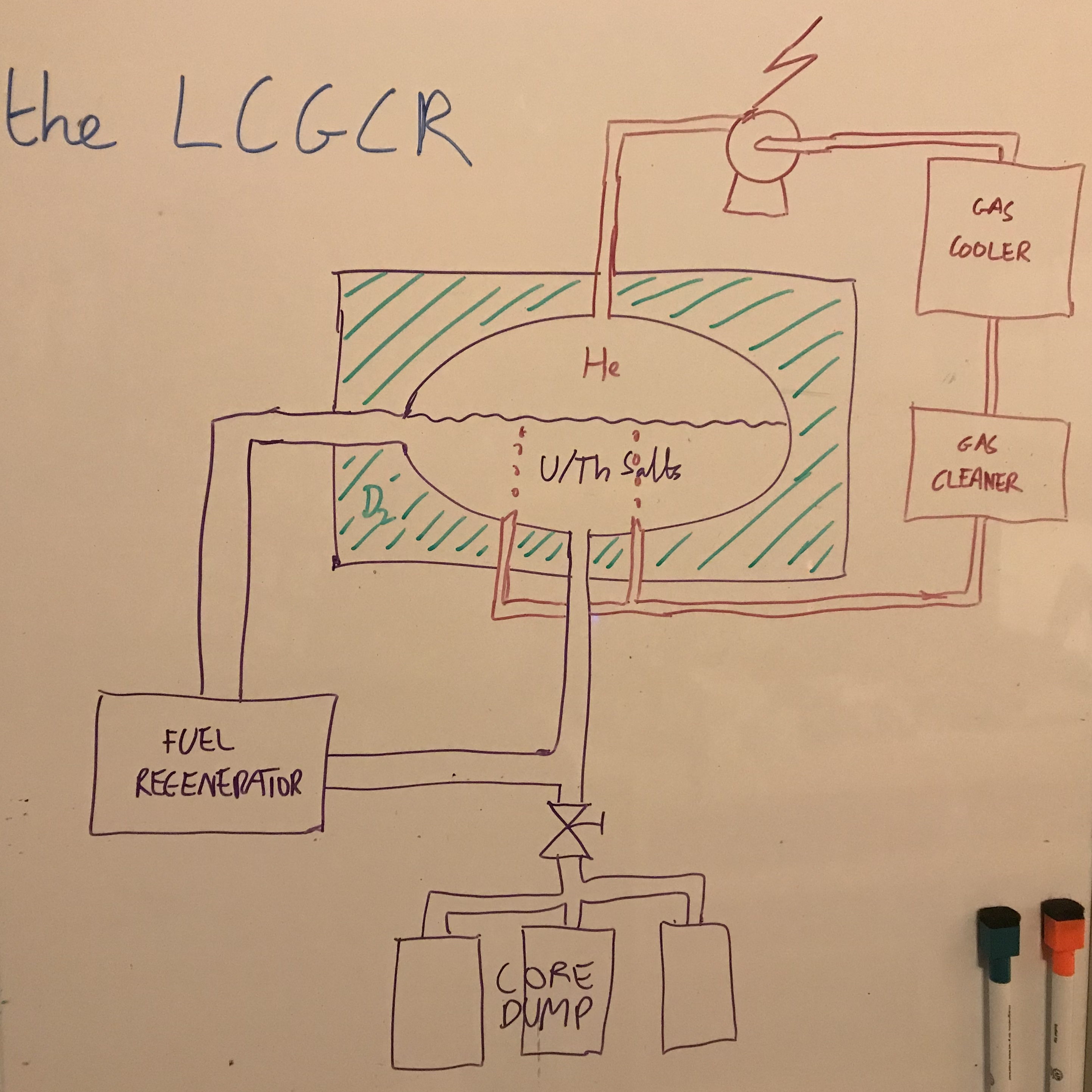
Herein is the not-yet-canonical result, and I invite physicists, nuclear engineers, and so forth, to tell me all the places I’ve gone horribly wrong. Behold the LCGCR: the liquid-core gas-cooled reactor!

Basically, it’s a liquid fuel design (I’m considering here solutions of uranium and/or thorium salts, rather than molten salts; probably in water, unless there’s a more convenient solvent available.) to take advantage of their self-adjusting reactor dynamics. The formulation of the fuel solution is such that it only achieves criticality when inside the calandria containing the deuterium oxide (heavy water – ignore the D2 on the diagram, that’s a writo) moderator; elsewhere in the fuel loop it doesn’t have that. (The details of the calandria – such as the precise arrangement of moderator around fuel – and the control systems for tuning the reaction are omitted in this diagram.)

20171218_070147975_iOS

The fuel loop itself is how we keep the reactor running continuously and maximize fuel use. The liquid fuel continuously circulates through the reactor and the fuel regenerator (heat exchangers omitted for clarity). The fuel regenerator is where we filter neutron poisons and stable fission products that won’t burn any more out of the fuel, and top it up with fresh salts as required, ensuring that we can use all of the U/Th we put in and all their useful decay products too.

(As a safety feature, we have the core dump valve located right at the bottom of the fuel loop. In the event of something going horribly wrong with the plan, opening this valve empties the whole fuel loop into a safe-storage system split across multiple tanks, set up so that none of them can possibly achieve criticality and all can handle the decay heat of however much of the core they get.)

We get the heat out for use by bubbling an inert gas (helium seems to be a good choice, given its low neutron cross-section and susceptibility to neutron activation, meaning the primary coolant loop is probably clean enough to run the turbines off directly) through the salt solution in the calandria. After running the turbines, we feed it through a gas cooler and a gas cleaner, which latter removes neutron poisons such as xenon, and other gaseous products of the nuclear reaction, before returning to the reactor.

This is of course a very brief sketch of a design which I haven’t spent all that much time thinking about, but it seems to me to be roughly plausible and to have a few interesting advantages. Your thoughts, sirs?

Lowari-class pinnace/shuttle

Yes, that means it’s bad sketch time again here at the Eldraeverse… so here, have an interface vehicle.

LOWARI-CLASS PINNACE/SHUTTLE

Operated by: Various starports and near-orbit stations; capital ships.
Type: Pinnace / shuttle (belly-lander)
Construction: Llyn Standard Manufacturing, ICC & various licensees.

Atmosphere-capable: Yes.
Gravity well-capable: Yes.

Personnel: 3 nominal, as follows:

Flight Commander / Sailing Master
Flight Engineer
Purser / Cargomaster

(Can operate with a single pilot.)

Passenger capacity: 24.

Drive: 2 x Jetfire Technologies trimodal NTRs
Propellant: Hydrogen slush
Acceleration capacity (nominal load): 4.3 G
Delta-v reserve: 18,300 m/s

Drones: None.
Sensors: Standard navigational suite.
Weapons: None as standard. (Militarized version can mount turreted point-defense lasers above and below the bridge.)

Other Systems:

Auxiliary power reactor (thorium pebble-bed).
Navigational kinetic barrier system.
Regenerative life support (atmosphere only).
3 x Bright Shadow flight computer systems
Small vector-control core and associated technologies.
Integral radiative striping.

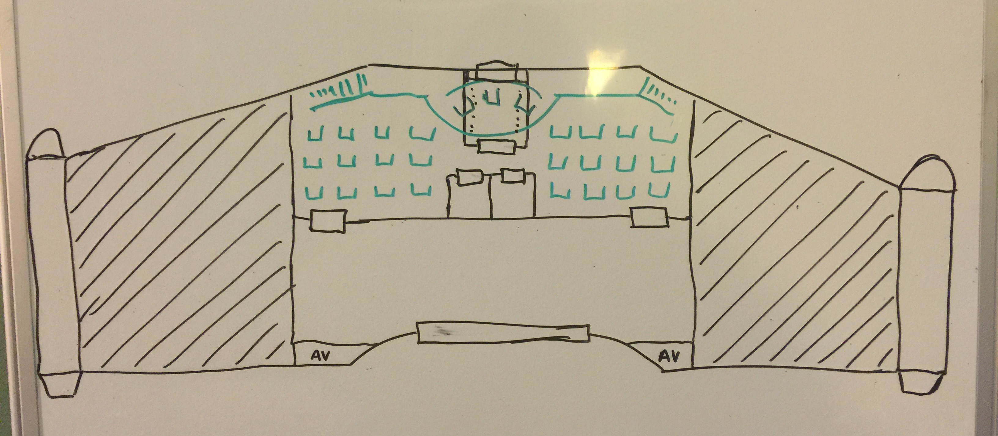
20150603_060009749_iOSAs can be seen from the picture, the Lowari-class is a very simple surface-to-orbit-and-back ship; flying-wing in form factor, with the entire habitable space occupying the center of the wing area, with fuel tanks outboard of that on each side, and the trimodal NTR engines on each wingtip. Flight control is primarily provided by thrust vectoring of the NTRs, but aerodynamic control surfaces and small attitude-control arcjets back this up.

The livable area exists on one single deck, which doesn’t include much in the way of dedicated machinery space; the machinery is squeezed into spaces behind access panels, primarily into the subdeck and behind the bulkheads of (in particular) the cargo hold. The largest of these are two dedicated avionics spaces (labeled AV) at the back of the cargo hold.

The for’ard half of the livable area is the passenger deck. As the ship’s not intended for long-term habitation, this means seats, not cabins;  large, comfortable, recline and put-your-feet up, quite-able-to-take-a-nap in leather seats with assorted luxury accessories, certainly – at least in the version they sell in Imperial markets, travelling like a gentlesoph and all that – but seats nonetheless. Three rows of four each to port and starboard; a total of 24 passengers.

This passenger area’s semi-divided by structures amidships. Going all the way floor to ceiling at the aft are two small compartments; a ‘fresher and what is, on the civilian model, a galley for serving drinks and snacks. (Military models may or may not keep this.) Ahead of that, and half-height, bearing in mind that the wing gets fatter towards the leading edge, is the airlock. It’s a fancy model with two operating modes: it has a conventional for’ard outer door designed to dock with other craft, but the floor also functions as an outer door; it’s designed to descend as a boarding ramp/boarding elevator when the Lowari is on the ground. (It can, of course, function as an actual airlock, even though the Lowari almost never does anything in space other than dock to/land in a bay of a larger craft.)

The flight deck is in the same compartment (indicated in green); it sits atop the airlock on a small platform of its own, where the three crew share one long console. It’s accessible by a long gallery leading to stairs on each side of the ship.

The leading edge of the Lowari‘s for’ard compartment, incidentally, is configured as one enormous picture window, because it’s not flying if you can’t enjoy the clouds on takeoff, the beautiful panoramas of space while in orbit, and the sheath of outrageously hot plasma trying to get in and incinerate you all on re-entry. Indulgent pilots may let well-behaved passengers come up and stand on adhere to the gallery to get a good view once they’re safely in orbit.

The aft compartment (accessible in-flight by doors to port and starboard) is the cargo bay, capable of housing eight or so standard cargo containers or an equivalent amount of breakbulk (including, say, the passengers’ effects). While said effects and suchlike are usually taken off via the bow airlock, there’s a large spacetight cargo door to aft/dorsal to allow large cargo to be loaded and unloaded. In space, this is often done by workpods, and the cargo bay is designed to depressurize for this purpose. (Conveniently, this also lets it serve as a backup airlock, if needed.)

Don’t go to space any other way!

The Kalantha: Revealed

So, the Kalantha-class frontier trader. The iconic ship of the small traders of the Expansion Regions. The commonly found – maybe a hundred thousand built – everysoph, jack-of-all-trades ship that needs only minimal external support and can function in any of a large number of roles. Needs only a tiny crew. Easy to keep running forever, if you’ve got a Flight Engineer who’s even half awake.

The Firefly-class of its ‘verse, one might say.

KALANTHA-CLASS FRONTIER TRADER

Operated by: Free traders, especially in outer regions, primarily Empire and allies.
Type: 
Atmosphere-capable multipurpose free trader.
Construction: 
Islien Yards (original); now licensed to multiple manufacturers.

Length: 42 m (forward hull); 96 m (propulsion bus)
Beam: 
16 m (forward hull diameter, not including radiators)
Loaded mass:
 [xxxxx]

Gravity-well capable: Yes (forward hull only).
Atmosphere-capable:
 Yes (forward hull only).

Personnel: 4, as follows:

Flight Commander
Flight Executive / Cargomaster
Flight Director / Sailing Master
Flight Engineer

Thinker-class AI.

Drive (forward hull): 3 x Jetfire Technologies trimodal NTRs
Drive (propulsion bus):
 Nucleodyne Thrust Applications 3×1 “Sunheart IV” fusion torch.
Propellant:
 Deuterium/helium-3 blend.
Cruising (sustainable) thrust:
 6.0 standard gravities (6.4 Earth G)
Peak (unsustainable) thrust:
 6.2 standard gravities (6.6 Earth G)
Delta-v reserve:
 [xxxxx]
Maximum velocity:
 0.1 c (based on particle shielding)

Drones:

4 x off-the-shelf camera/maintenance drones

Sensors:

1 x standard navigational sensor suite, Cilmínar Spaceworks

Weapons:

None.

(Well, technically.

On each outer engine fin, the Kalantha-class has a hardpoint for aftermarket… freight handling equipment. Yeah, that’s the ticket. Freight handling equipment.

If you’re registered somewhere with halfway civilized attitude to shipboard arms and flying either likewise or in free space, then there’s absolutely nothing to stop you from ordering up a couple of mass drivers and mounting them here. Hell, the shipyard you get the ship from will be happy to do it for you. You would still be incredibly ill-advised to get your Kalantha into a scrap with anything resembling a real warship, but it is often sufficient to divert would-be pirates towards freighters registered in enforced-helplessness regimes.

If, on the other hand, you’re venturing into some of those and they’re inflexible when it comes to enforcing their law on visiting starships, there are any number of small yards offering genuinely innocent items of equipment that can be mounted to these hardpoints and yet which will make a nasty dent in a would-be attacker with just a few disabled safeties, simple mods, and trivial software changes, which they will be more than happy to instruct your engineer in how not to do accidentally. Be creative!)

Other Systems:

  • Cilmínar Spaceworks navigational kinetic barrier system
  • Biogenesis Technologies Mark VII regenerative life support
  • 3 x Bright Shadow EC-720 information furnace data systems
  • Islien Yards 2C vector-control core and associated technologies
  • Systemic Integrated Technologies dual-mode radiator system
  • 3 x modular hardpoints

Small craft:

1 x Élyn-class modular microcutter, in forward-mounted hull-pod (without module; modules can be stored in main hold)

DESIGN

If you were expecting something as sleek and shiny as the Drake, sorry. The Kalantha works for a livin’. (Well, okay, actually it is quite shiny, despite being lived-in – and won’t it be fun to try and achieve those two visual effects at the same time – due to the wonderful nanotech-type maintenance procedures. Sleek, on the other hand, less so.)

The Kalantha needs to be able to operate within gravity wells, in atmosphere, and otherwise across the interface line, because its explicit design goal is to service worlds that don’t necessarily have highports, and certainly don’t have developed starport facilities. This is, unfortunately, sadly in contradiction to its other design goal of being a good, efficient interplanetary/interstellar craft.

The Kalantha squares this circle as best it can by being two ships in one; an atmosphere-capable, landing-capable forward hull that doubles as the interface craft, and a propulsion bus that holds the fuel and drives necessary for interplanetary travel that can be left parked in orbit while the forward hull lands and goes about its business.

FORWARD HULL

The forward hull of the Kalantha is the classic just-on-the-cone-side-of-cylinder-with-a-rounded-top – bullet-shaped, you might say – tail-lander hull, with a few minor variants. It has three modest radiator fins (the low-power radiators) extending from it, 120 degrees apart, one of which – the one with the yellow navigation light – we shall designate as indicating the arbitrary dorsal direction of the ship. Each of these fins, in turn, terminates at a vectorable engine pod, complete with iris-domed intake at the for’ard end and cascade vanes at the after end, housing one of the three trimodal NTRs which drive the forward hull when operating in uncoupled mode. Outboard of those are reaction-control assemblies, navigation lights, and the hardpoints.

On the opposite side of the ship, the arbitrary ventral, and filling most of the space between the other two radiator fins, are the two sets of cargo doors, opening on the lowest two decks; between the two doors is the eye of a tractor-pressor emitter to assist in loading. The lower of the two cargo doors comes complete with an extending ramp and a small “postern” door built into it for sophont boarding without having to open up the whole thing. Above both doors, on the next deck up, there’s a small streamlined structure taking up about a third of the inter-fin space in the center, with a rounded for’ard and 45-degree after cut-off, with windows facing out and down; that’s the quarterdeck/cargomaster’s office, situated where it can keep an eye on loading and the ground airlock.

Right up top, two symmetrical, cylindrical towers rise from the hull at the dorsal and ventral, each ending about a meter short of the bow. The one at the dorsal side has more than a few antennae and other communication widgets attached, and is topped by a circular dome window; the one at the ventral does not, and ends in a domed iris-opening. The rounded bow of the ship is a geodesic dome-window, stellarium-style; right in the center of this, where the axial shaft (see below) terminates at the bow, is a for’ard airlock for in-space use.

The rounded base of the ship, in uncoupled flight, is covered by a folding, iris-style heat shield. When retracted, this covers both (around the edges) the ship’s ruggedized landing gear, and (in the center) the coupler that connects it to the propulsion bus; including an aft spacetight door (not a full airlock) where the axial shaft ends, along with internal linkages for life support and fuel transfers, along with redundant power and data bus connections.

INTERNAL LAYOUT

The internal layout is also classic tail-lander. The layout is arranged to function under gravity – whether planetary gravity or thrustdown in either coupled or uncoupled mode – but the ship’s systems are designed to function equally well in microgravity. Whether it does or not, well, that’s up to the taste of the individual crew.

The Kalantha-class is a nominally seven-decked ship, with all decks linked by an axial shaft running through the ship from bow to stern along the thrust axis, from the airlock at the bow (used to dock when in space) to the spacetight door aft that connects to the propulsion bus. The shaft contains a spiral stair running from one end of the ship to the other, and an elevator platform likewise; in microgravity, of course, you can simply float up the shaft. The shaft walls, apart from primary structural members, also contain the main power and data buses.

The lowest – or aftmost – two decks are the cargo bay; each level, as noted above, having its own cargo door to ventral. The cargo bay can function as either one deck or two; the only permanent structures on the second level are access catwalks, but the structure is designed to accept gratings which clamp into position between the catwalks, converting it into a true second deck. (This is common practice if you’re transporting small breakbulk rather than containerized cargo or large breakbulk.)

The next two decks are the engineering space; again not physically separated except for the second-level catwalks. The majority of the ship’s machinery is concentrated here: the vector-control core, the gyros, the auxiliary power reactor, the life support systems, the robot hotel, and the bunkerage and other tanks. The lower engineering deck also contains the above-mentioned quarterdeck at its ventral edge; the bunkerage is clustered around it and the corridor leading there from the axial shaft to cut down on machinery noise.

The top three decks are all sophont-oriented. The lowest hosts a small workshop space, two ‘fresher, and (usually) six modest cabins; enough for the crew and a couple of passengers. (Kalantha-class ships expecting to or chartered to carry more passengers usually handle the situation by installing some containerized people-pods and auxiliary life support down in the cargo bay.)

The next is the base of the two bow towers. To dorsal, the tower base holds the computer core and avionics equipment; its windowed extension bow-ward hosts the bridge/conning station. (Often, this is only manned during maneuvers; routine systems management can be done from almost anywhere on board.) To ventral, the tower serves as a (close) bay for the ship’s Élyn-class microcutter. Most of the rest of the deck is divided between the ship’s locker, galley, and medical bay, surrounding a small central common area.

And the small topmost deck, beneath its stellarium dome – again providing the vital service of stopping people from going tin-can crazy – is in its entirety the ship’s primary common area. Small inter-deck openings surrounding much of the central shaft provide convenient accessibility to the small central common area on the lower deck.

PROPULSION BUS

By comparison, the propulsion bus is very simple in layout; it begins with a broad, stubby truss to which the various auxiliary machinery of the propulsion bus is clamped; inside this right at the front end is mounted the small maneuvering pod, which combines a small piloting station for the propulsion bus alone with some of its diagnostic and avionics equipment, and a rear airlock permitting access down the truss. A for’ard spacetight door matches up with that at the stern of the forward hull when the ship is coupled. This region also contains the extendable remote antenna that permits the propulsion bus to be remotely controlled when it’s uncoupled.

Internally, the maneuvering pod is very simple; the for’ard hatch/window permits one person to access the conning seat located immediately behind it. Turn the seat around, and further back in the pod are some racks of avionics and diagnostics, a minimal commode (which flushes stored waste into the forward hull’s life support system when the ship couples), a mini-fridge for rations and potables, and the canned life support machinery (which likewise flushes and recharges when the ship couples). Right at the aft end is an airlock leading out onto a ladderway down the truss.

(Bear in mind that the maneuvering pod is never manned in normal operations; it exists only for (a) engineers while they’re running diagnostics or doing maintenance; and (b) when you’re landing somewhere that ain’t civilization in the strictest sense, and so you want to leave someone behind in the propulsion bus just in case any of the locals get clever ideas and need to be taught the Kzinti Lesson…

…they don’t mention that second application in the brochure, but they do imply it pretty well.)

Behind this the truss gives way to the structure wrapping the two giant spherical tanks containing the propulsion bus’s deuterium and helium-3 supplies; attached to the outer surface of this wrapping structure are the main high-power radiators for the fusion torch.

And then behind them is the shadow shield structure and the fusion torch itself.


Nelyn-class Deck Plan

20150328_231228194_iOSBecause I couldn’t stop scribbling during my final formatting pass, okay?

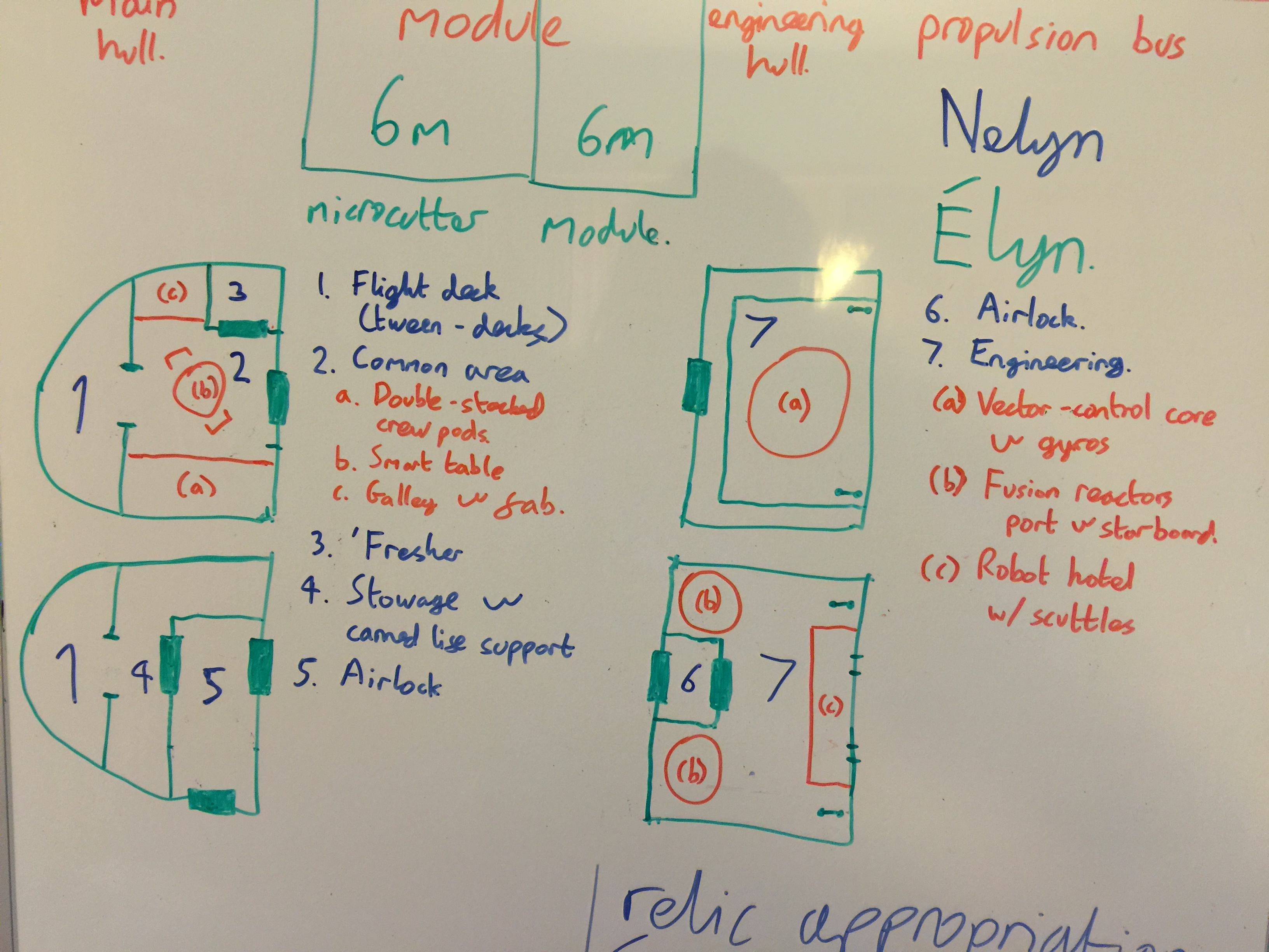
Main hull:

1. Flight deck, right for’ard, and not on either of the decks strictly speaking, since it’s in the nose of the craft in what amounts to a transparent dome. The pilot’s command seat is, essentially, centered exactly on the fore-to-aft drive axis. Openings above and below provide access to both decks.

2. The common area, on the upper deck, ending in the for’ard upper level module access. Includes two stacked crew pods (a) to port, for the crew to sleep; a smart-table (b) for miscellaneous work, administration, and recreation purposes, and (c) a galley and fab unit to starboard…

3. …for’ard of the ‘fresher.

4. Most of the lower deck is a single compartment, which includes avionics equipment and canned life support (to starboard) and racked stowage space (to port), although most of the port side is taken up by…

5. …the airlock, an unusual three-door design that doubles as the for’ard lower level module access as well as the boarding airlock and an airlock providing convenient access to the module volume when no module is installed.

Engineering hull:

6. The airlock/aft lower level module access provides access to the engineering hull when no module is installed. It leads into…

7. The engineering section, which is primarily a single large chamber. The upper deck only exists as a catwalk running around the perimeter of the chamber, and the aft upper level module access is a simple spacetight door that cannot be opened when no module is installed. Primarily notable in the engineering section are (a) the vector control core and reaction wheels, (b) the port and starboard auxiliary power reactors, and (c) the robot hotel, with scuttle access to the propulsion bus for external maintenance mechs.

(Note: The Nelyn uses canned life support because it’s basically a local ship; the vast majority of them in use are not in roles that require them to ever venture very far from a source of resupply. Those who’d like to use their Nelyn for a long interplanetary or even interstellar voyage, on the other hand, aren’t left out; they can simply plug in the “accommodation” or “luxury suite” module, say, that by design comes with its own regenerative life support and possibly even hydroponics…)

Nelyn & Élyn

2015-03-27Usually I prefer to avoid inflicting my dire drawing skills upon y’all, but what the hell, I’ll make an exception this once.

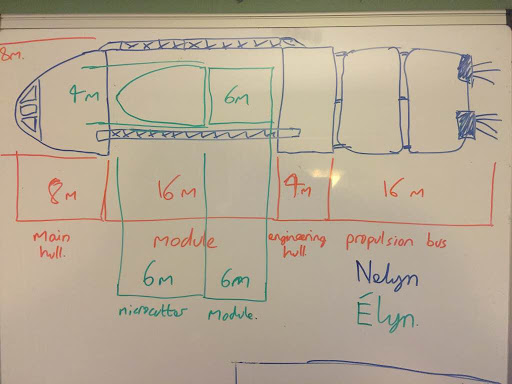
The diagram to the right is my quick size sketch of the aforementioned Nelyn-class modular cutter (in blue) and the Élyn-class modular microcutter (in green).

As you can see, the Nelyn is the big one, inspired by/a harder version of the Traveller RPG’s modular cutter; an interplanetary craft that’s the workhorse of the Empire; 8 m in diameter, and 48 m long in total; an 8 m main hull at for’ard for the flight crew, the 16 m module space; a 4 m engineering hull for sensitive machinery; and the 16 m propulsion bus at the back. The module space is bridged by three trusses 120 degrees apart, the dorsal one of which is split in the middle and folds back to allow module swapout. And there are lots of different modules for pretty much any purpose you can think of.

The Élyn is the smaller one, only 4 m in diameter and with a 6 m hull (including engines), optionally taking a 6 m cylindrical module in a rear-mount. It’s strictly a local-orbit craft without interplanetary capability (although it is capable of take-off and landing on many planets) – but the reason it’s drawn where it is is that there is a Nelyn module specifically designed as a cradle for the Élyn, letting an entrepreneur with the former make pretty decent money providing a taxi service for the latter on long trips…

Drake-class Frigate: Post-Hoc Modifications

Because despite this and this, there are always a few modifications once you actually start beating brass and doing detail work:

The 4 x “Slammer III” dual turreted mass drivers have become 2 x “Slammer III” duals and 8 x “Slammer III” singles, four up front, two in radiator-tip (wingtip) leading-edge mounts, and two rearward-mounted to protect the ship’s kilt;

The aft landing bay door is now dropped and replaced with two side-opening landing bay doors for’ard of the radiators, since the former would have required flying directly through the high-radiation zone of the torch drive and said thermal radiators to use; much easier to fly parallel and dock sideways. This, in turn, has enabled the transformation of the back of the landing bay into dedicated cargo/storage space, with said side doors being in an excellent place for loading when the ship is landed or docked.

And after consideration of the practical height of the landing bay vis-a-vis the size of the Nelyn-class modular cutter, I’m swapping it out for a pair of Élyn-class modular microcutters (a gig-sized craft); if you want a really pretty good visual reference for that, think of it as looking like a rebranded SpaceX Dragon V2, with the cylindrical module in place of the trunk.

The Drake: Revealed

So let’s talk about the layout of that mainstay of the Imperial fleet, the Drake-class frigate. (The numbers are for deck plans. My own sketches are far too horrible to publish, but… well, there they are.)

External

Like most starships, one could conveniently divide the Drake-class into a pressure hull and a drive bus. It’s a little harder to spot the connection than it is on many ships (like, say, the Cheneos-class freighter) because of the armor, but it’s still there.

The pressure hull is, essentially, the front half of the ship, a round-fronted, slightly-flattened cylinder, for the most part unbroken in its organic curves except for the few openings (stellarium, gun port, airlocks) mentioned below, for the six geodesic spheres – three on each side, arranged fore-to-aft along the mid-line – clamped to the hull, which contain redundant sensor suites, best not placed inside the armor, the four paired cheek-mounted light mass drivers to for’ard, the ship’s secondary weapons, and an antenna suite projecting from the dorsal pressure hull near its after end.

Behind this, the pressure hull stops, but the armor which covers it continues on past the aftmost pressure bulkhead, broadening the hull to port and starboard even as it narrows into the starship’s stubby “wings”. (Which are of course not wings – they’re the secondary radiators; double-sided radiative striping under transparent light armor, encapsulating more bunker space. These are considered the secondary radiators because they’re designed to carry only the life-support and low-power heat load.) The armor back here serves as a cowl wrapping around the propulsion bus, which is the usual tangle of structural trusses, cryocels (for the ship’s limited supply of afterburner antiprotons), spherical and cylindrical tanks (for deuterium/He3-slush fuel and heat-sink goo), auxiliary machinery, and at the aftmost end of that (such that the bunkerage provides additional shielding for the crew), the fusion torches sticking out the open back of the cowl.

(This is, of course, a weak spot in the starship’s armor, but such would the drives be wherever you put them. In practice, the argument goes, when you’re in the furball – well, million-degree drive plasma provides a poor approach vector even for a kinetic weapon, and when you’re not – well, just watch where you point your kilt, okay?)

The external parts of the primary radiators sit on top of and below the cowl; they’re liquid-metal droplet radiators, which extend perpendicular to the secondaries when in use. They’re intended to support full power-and-some-more on the reactors, such that you can make a fast retreat and chill down your heat sinks at the same time.

The lowest deck extends, squared-off and flat-bottomed, a little below the main body of the pressure hull and extends back some way below the cowl; as the large doors at front and aft would indicate, it’s the landing bay.

The hull itself is gorgeous in shimmering military indigo; naturally, leading edges and other salient points are highlighted in intricate swirls of embedded gold-filigree brightwork, just because the IN can and wishes to emphasize that small point. (Close inspection will also note the apertures of attitude-control system thrusters, especially to outboard for the largest moment arms, and scattered black, glassy domes concealing the point-defense laser grid.)

Internal

Internally, the Drake has five decks dorsal-to-ventral. It uses the classic belly-lander arrangement because it’s considered possible to land a frigate planetside, or at least small-planet-side, or operate in atmosphere. (In the latter case, under the “with sufficient thrust, pigs fly just fine” principle.) Frigate captains rarely want to, though.

Despite that, there’s no artificial gravity on a Drake; while in space, the starship operates in microgravity.

Communication between decks is provided by a pair of elevators/shafts running between decks 1 to 4, and a staircase providing access to deck 0, along with various maintenance ladderways and such (especially in engineering). The elevators don’t run under microgravity conditions; they’re only for use under gravity. Rather, the elevator car is open-topped and is locked down on deck 4 in flight, allowing the shafts to be used as any other passageways.

As far as possible, auxiliary machinery, further storage tanks, etc., are wrapped around the outside of the ship, between the decks and the hull, to use as additional protection in the event of an armor-penetrating strike.

Deck 0

Deck 0, “the loft” is the smallest deck, squeezed in between the ceiling of deck 1 and the hull. Fortunately, it contains (for the most part) spaces which will be unmanned at general quarters or higher readiness states.

Specifically, at the fore end, there’s (1) the captain’s cabin, including a small office and private ‘fresher, from which a central corridor runs aft past (2) and (3), VIP staterooms which include the ‘fresher but not the office, ending at (4) the auxiliary sensory and communications room (approximately beneath the antenna suite mentioned above. Outside this room, a foldaway spiral staircase (i.e. serving as a microgravity shaft in flight) descends to the main corridor of deck 1.

Deck 1

Deck 1 is the first of the three “main” decks of the pressure hull.

Starting from the for’ard end, we begin with (5) the stellarium, which is literally the only room on the ship with windows, of which it has a continuous strip around the periphery and overhead. It also, being intended to entertain visitors and provide somewhere to get away from inside for a moment, comes with comfortable microgravity-adaptive seating, a few potted plants, and a wet bar.

More important for military purposes, while the windows are tough, they aren’t that tough, and as such the armor layer passes comfortably behind it, and access is through a sequential pair of spacetight doors. Naturally, it’s unmanned at general quarters or higher.

Behind this, another central corridor runs aft past (6), a conference lounge to port, and (7) an office for ship’s business – usually the Flight Administrator’s domain – to starboard, reaching the for’ard entrance to (8) the bridge/CIC, which takes up the full width of the ship in the center of the deck.

The aft entrance to the bridge/CIC opens into a second central corridor, this time passing (9), the server room containing the ship’s primary “dumb” servers and avionics systems to port, and (10), the ship’s AI’s cogence core and primary mentality substrate to starboard, terminating in a five-way junction containing the access to deck 0. To port and starboard, a cross-corridor terminates at the elevators/shafts, each with a ‘fresher located adjacent; aft, a door provides access to (11) the maneuvering room, in the form of a well-insulated gallery overlooking (12) the engineering space, which spans all three main decks.

(Secure backups for the cogence core and the substrate also exist buried in the middle of the propulsion bus section.)

Deck 2

Deck 2 is the central deck of the ship, and to a large extent is divided into two non-communicating parts. As a frigate, the Drake-class is built around its main gun, which occupies the axis of the ship and thus the center of the deck. While access is possible to the mass driver chamber (which can even be pressurized, with the gun port in the bow closed, for maintenance), it’s normally kept evacuated and is not, in any case, a very comfortable place to be.

The mass driver runs down the center of the deck from the gun port at the bow to (13) its “breech”, which sits directly against the engineering space bulkhead. Straddling it on either side are (14), the magazines for its k-slugs, which are also kept evacuated under normal conditions for ease of autoloader operation.

Starting this time from the aft end of the ship, at far port and starboard against the engineering bulkhead are the elevators/shafts and the associated adjacent ‘freshers, and the accesses directly to the engineering space. Corridors lead forward from these against the inner hull until they pass the magazines, at which point they turn inwards to reach, and proceed to the bow against, the central mass driver (for ease of accessing the driver coils for maintenance from these corridors).

On the port side, the majority of the space for’ard of this corridor is given over to (15) the medical bay, and at its for’ard end (16), the nano/cryostorage unit, used both for patients in need of return to fuller hospital facilities and doubling as the ship’s brig.

(It should be noted that the medical facilities are quite limited; the nature of the space combat environment is such that the window between “fine” and “chunky salsa” is quite narrow, and as such the medical bay is oriented more toward treating illness and minor injuries among the crew than it is to handling massive combat casualties.)

On the starboard side, the equivalent space is used for (17), a combined laboratory, workshop, and engineering support area.

The remainder of the space for’ard of these, behind the avionics area at the bow, contains the equivalent of two small rooms on either side (18, 19, 20, 21), connected by double spacetight doors; this is the modular function area. With sufficient engineering support and at a yard, these independently-encapsulated areas are designed to be disconnected from the ship’s infrastructure and framework, pulled out as a whole – along with their associated outer-hull plate and armor – and replaced with other modular capsules of equivalent specification. This feature permits the Drake-class to be customized for special functions – such as the electromagnetic radiation shielding we saw at the Battle of Eye-of-Night – much more flexibly than would otherwise be possible.

As mentioned, main access to the (12) engineering space is on this deck, although catwalks lead up and down to the lower level and to the maneuvering room gallery. The nearer part of the engineering deck contains a variety machinery, although also housing to port and starboard the two auxiliary fusion plants used to provide power to the starship when the drive is shut down. Beyond it, a half-octagon wraps around the bulk of the vector-control core and the reaction wheels, containing in their own sections the (22) life support systems to port, and the (23) robot hotels for the ship’s mechanicals to starboard.

Amidships between these, a small airlock and external robot hotel provides access to an unpressurized maintenance crawlway running through the propulsion bus. Normally, this is only used by robots or for occasional yard maintenance; radiation levels are unhealthy back there with the drive running, to say the least, but access may be necessary in emergencies.

Deck 3

Deck 3 is primarily the crew deck. At the for’ard end, along the centerline, is the (24) mindcast receiving room, allowing visitors received as infomorphs to borrow one of the ship’s spare bodies for the duration of their visit; aft of that, a cross-corridor links the (25) port and (26) starboard airlocks, each of which is accompanied by a small conning station (usually disabled) for use while docking.

Aft of that, another small room serves as a quarterdeck/reception area and security post. From there, a central corridor leads aft through the (27) crew quarters – the corridor itself is lined with access hatches to what are, in effect, double-sized personnel capsules – to the (28) comfortably furnished mess deck, which incorporates a (29) standing galley to port, and the (30) ship’s locker to starboard. Beyond the mess deck, hatches to port and starboard – a design choice permitting a large screen to be mounted on the mess deck’s after bulkhead – lead through inner-hull-hugging corridors past the (31) accumulator room to port, and the (32) auxiliary control room and (33) a small gymnasium to starboard, to another cross-corridor against the engineering bulkhead, providing access to the elevators/shafts and the ‘freshers on this level. However, there is no routine access to the engineering space on this deck.

Deck 4

Deck four, slung beneath the ship, is primarily its (33) landing bay; one large space, extending fore to aft. Space is reserved at port for the (34) armory, used to equip shore parties if necessary, and at starboard for a (35) second workshop space. These are each located for’ard of the elevators/shafts which open into a small hallway offering access both to these, and to an airlock opening into the landing bay. There are no associated ‘freshers on this deck.

A Drake-class frigate is typically equipped with a single cutter, an interface vehicle, or both; the relatively large landing bay permits it to also store the frigate’s complement of drones, and to serve as a cargo bay to such extent as space permits. Overhead manipulators permit vehicles to be moved to engage with either the fore or aft mass catapult for launching, reshuffling of the cargo, or retasking of the cutter, as desired.

Flight operations are handled from the bridge/CIC. The bay can be pressurized with both doors closed, but at general quarters or higher readiness states operates unpressurized to expedite operations and avoid unnecessary risks.

(For those paying attention to the implications: yes, the very same vector control tech that lets you make kinetic barriers lets you make nice air curtains that would hold air in even with the door open, while still letting you fly in and out. [Well, mostly: for molecular statistical reasons, they leak, but it’s manageable.] Some civilian ships use those for the convenience. Military ships prefer not to have unexpected depressurization incidents when someone gets a lucky shot in on the emitters when they don’t have to. Sure, it’s a pain to have to wear a skinsuit all the time, but you’re in the Navy now! Also, you’re less likely to get brained by a flying spanner if there were to be a curtain oops.)